How to Measure and Influence Fan Noise
Noise Measurement
Noise is typically expressed either as a Sound Power Level (LW) or as a Sound Pressure Level (LP).
- LW : The sound power level is the acoustic power emitted by a source. It is difficult to measure, but it is independent of the measuring setup (room, distance, etc..). It is expressed relative to a reference Wref = 10-12 W
- LP : The sound pressure level expresses the amplitude of the pressure wave (the loudness). It decreases with distance, and it is affected by reflections. As a result, it is not an absolute description of the sound source, because the measuring setup must be described as well. It is expressed relative to a reference Pref = 20 mPa
Not all frequencies are equally audible by humans, therefore the LP is often expressed as an adjusted value, offset by a weight (which depends on the frequency, see Table 1).

The sound pressure level is the most common equipment sound specification parameter, and since it depends on the measuring setup, there are some standardized guidelines on how to evaluate it. Levitronix uses the SEMI S2 guidelines, and specifies the conditions in the BFS User Manual (see Figure 1).

Using the following equation, it is theoretically possible to estimate the sound power level from the sound pressure level, but the result should be taken as indicative. In that calculation many factors might be uncertain, among which the directivity factor Q, the area of the surrounding surfaces S and their average Sabine absorption coefficient alpha.
Parameters of Influence for LP
As shown in Figure 1, the loudness of the fan increases with the rotational speed. For a certain fan increasing speed, the following law applies:
As a rule of thumb, increasing the speed by 10% causes a sound pressure level increase by 2dB (see Figure 2).
For geometrically similar fans operating at the same speed, the following applies:

Noise Control
Noise can be minimized acting on the source (the fan), on the transmission path (air ducts and structure), or on the receiver (the people surrounding the fan).
Acting on Noise Sources
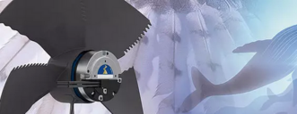
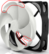
As mentioned, fans generate noise due to turbulence and vortexes. Certain manufacturers specialized in low noise fans by designing stators and rotors which minimize the vortexes, or that generate noise at frequencies not audible by humans. Such fans are often referred to as “bionic”, because of their geometries inspired by nature. These fans find applications in those settings where background noise must be minimized (recording studios and labs), or where many fans are present (data centers, server farms).
Acting on Noise Transmission Path
Air ducts absorb and transmit part of the noise, hence wrapping them in absorbing material might help to reduce vibrations.
Certain air ducts can host silencer units, which feature complex air paths, where the noise is absorbed. The working principle is similar to that of a gun silencer.

Flexible connectors might also result useful in de-coupling vibrating elements, so that transmission paths are broken.

Acting on Noise Receiver
People exposed to noise can be prompted to use earplugs or earmuffs, but this is often the least effective and least accepted solution.