NPSH required
What is NPSHr
NPSHr (Net Positive Suction Head required) is the amount of pressure (expressed in meter of water column) needed by the pump inlet to avoid cavitation.
Cavitation can be more or less problematic for the pump and process depending on how intense and extended it is. Therefore, there are multiple criteria available to calculate the NPSHr, the most commonly used is the NPSH3. Levitronix uses this criterion as well in the pump characterization process, so it will be described more in detail in the next section.
NPSH3 is based on the principle that a small amount of cavitation is acceptable, as long as the pressure loss is no more than 3% of the nominal performance.
Other NPSHr measurement criteria rely on the same principle but using different thresholds (pressure loss equal to 1% or another percentage), or on other principles. The most common alternatives are acoustic measurement of the characteristic noise, visual observation of the cavitation onset, analysis of the amount of debris detaching from the impeller, visual analysis of the abrasion of the impeller blades, drop in pump hydraulic efficiency.
NPSH3 measurement method
NPSH3 is calculated as follows: a closed loop is built as in the diagram in Figure 1. At first, the valve upstream of the pump is maintained fully open, the pump is running at a certain constant speed, and the downstream valve is partially closed to set a certain flow. The pressure difference between up- and down-stream of the pump is measured and noted.
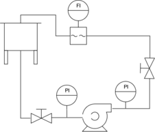
As a next step, the upstream valve is gradually closed (causing a decrease of the inlet pressure). To maintain the same flow-rate, at the same time the downstream valve is gradually opened (causing a decrease of the outlet pressure). The two valves have to be regulated so that the flow-rate remains constant during the whole measurement.
Since the pump is running at the same speed and producing the same flow, the pressure difference Pdiff generated should be identical.
In case of cavitation, the Pdiff will decrease. When it becomes 3% lower than at the beginning of the test, we have met the target cavitation criterion. The pressure at the inlet of the pump is now noted, the corresponding absolute pressure is calculated and converted in meters of water column. This will be the NPSH3 for the selected combination of speed and flow-rate.
The process is now repeated with the same rotating speed, but for another flow-rate. Once sufficient NPSH3 points are measured for a certain speed, the process is repeated from the beginning for another speed.
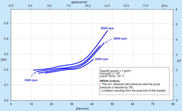
As a result, there will be a chart plotting the absolute pressure needed to avoid cavitation, for any working point of the pump (as in Figure 2).
Other operating points
In Figure 2, it is possible to notice that some pump operating points are not charted (e.g. for flow rates <10 lpm, for speeds <5000 rpm, etc).
There could be multiple reasons for this lack of completeness:
- No cavitation happens. It is possible that for some flow rates the 3% pressure loss criterion was not reached, therefore no NPSH3 value can be determined.
- No precise value could be determined. In particular at low speeds, the absolute pressure needed to avoid cavitation can be so low that it cannot be measured accurately with the current instrumentation. If the measurement error is in the same order of magnitude of the measurement itself, the result could be misleading and not relevant for practical purposes.
- Unstable operation. In most “normal” conditions the pump can operate in a stable way over a very extended flow range. In the cases where the inlet is throttled to intentionally cause cavitation (as in our experiment), it is possible that the pump becomes unstable before the onset of cavitation. For example, if the impeller gets axially displaced above safety limits, the pump will automatically reduce the velocity, so the NPSH3 cannot be measured.
Some other operating points are not charted for clarity, for example in the case of intermediate speeds. In the case shown in Figure 2 (smooth, continuous, separated line), the NPSH3 of intermediate speeds can be obtained by interpolation. There are pumps with more complicated charts, such as in Figure 3.
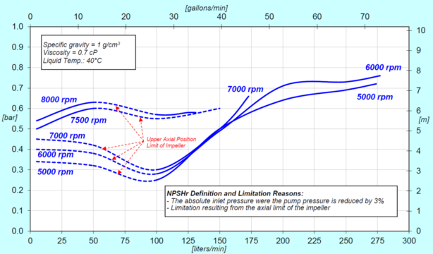
Figure 3 shows how for certain flow-rates the NPSH3 is calculated or derived under unstable conditions.
What parameters affect NPSHr
Since the temperature affects the vapor pressure, an increase of temperature will require an increase of absolute pressure to avoid cavitation. From the practical point of view, this means that the NPSHr curves get shifted upwards in case as the fluid temperature increases.
The micro-bubbles present in the fluid act as a starting point for cavitation, therefore they must be minimized. Pumping foamy fluid, or strong mixing in the upstream tank can pose a challenge in these regards. Whenever possible, it is important to de-aerate the fluid before pumping.
The density affects the intensity of the hammering effect, and therefore it is particularly important to respect the NPSHr safety margins.
Viscosity has an effect on NPSHr only when it is very large (in the case of heavy oils for example). Otherwise the other parameters have a larger effect.