Operating Range and Stability
Levitronix fans could theoretically operate in all four quadrants of the Flow-Pressure chart. In fact they can rotate in both direction (clockwise, and counterclockwise), and they can both boost or brake an airflow. In reality, they are characterized to operate with the flow in a certain direction (in the two right quadrants of the chart, see Figure 1).

In the Flow Pressure chart in Figure 1 there is an orange “Stability Limit” line which defines the right-hand edge of the operative range. If the fan is installed in low-resistance setups, the system load will be so low that the pressure difference generated by the fan will be close to zero. Without an axial load, the fan will easily wobble (the tension from the passive magnetic bearing contributes to stability), and in a matter of a few seconds it might crash and go in error state.
Stalling Region
Most axial fans, blowers and compressors suffer greatly from stall. Stall is an aerodynamic instability phenomenon of the machine, where the streamlines of the flow detach from the blades, vortexes appear in the channels between the blades, and the pressure generated drops. During stall, the bearings are subject to vibrations which lead to mechanical failure. Levitronix bearingless fan systems are partially immune from the problem, because the magnetic bearing is not affected by vibrations, so they can operate even when partially stalled.
However, stall does indeed reduce the performance of the fan, because part of the blade span generates no pressure, and might allow some local re-circulation.
Stall typically appears at the working points characterized by high rotational speed and low flow rate. The characteristic of the stalled region is highlighted in red in Figure 2. In this region, stall explains the “bathtub shape” of the flow pressure curves.
The band between the stalled region and the Stability Limit is the operating range where the fan is most stable, performing, and efficient.


Counter-Rotating Stall
It is worth to take a deeper look at the origin and propagation of stall. Stall happens when the flow streamlines detach from the blades and cause vortexes. This happens when the geometric features of the blades (mostly the angle of the leading edge) don’t match with the velocity triangle of the flow. Certain machines (airplane wings, wind turbines, etc..) have variable geometry to adapt to changing flow conditions. Most rotating machines, however, have fixed geometries and can incur into stall.

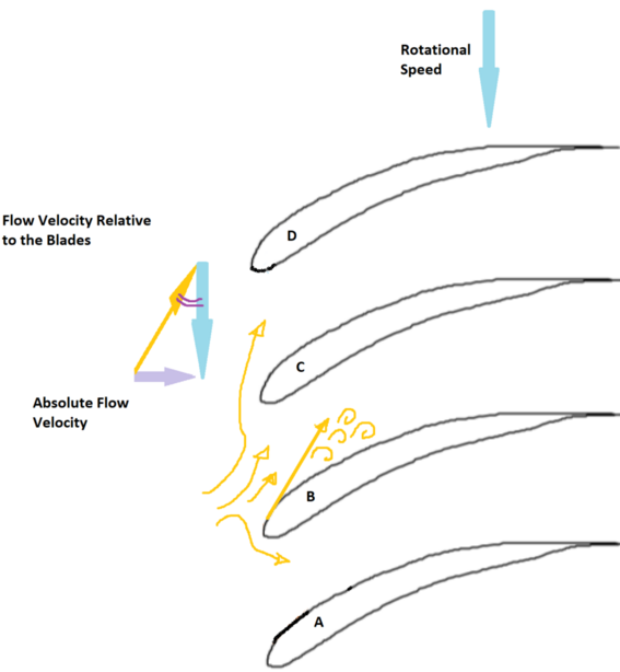
The origin and propagation of stall is explained in Figures 4, 5, 6. In the case of high rotational speed and low flowrate (as in the red section in Figure 2), the velocity triangle (composed of absolute flow velocity, blade velocity, and flow velocity relative to the blade) won’t match the blades angles anymore. When this happens, the streamlines will detach from the blades, and vortexes will appear in the channel. Because of the vortexes, the channel will be partially obstruct, and the flow will be directed to the previous and to the following channels.
In the first case, the incoming flow will prevent streamline detachment, while in the second case it will contribute to it. As a result, the stalled sector of the fan will propagate in direction opposite to the rotational speed (hence the name “counter rotating stall”). The propagation speed is typically lower than the fan rotational speed, so the stalled sector will appear as rotating to an external observer.
Since the stall sector periodically hits each blade, it can be a source of vibration noise, mechanical stress (which can lead to high cycle fatigue in conventional fans).
On top of this, since no pressure is generated by the stalled channels, they act as a path to back-flow.
Instability due to Installation
Even if the fan operates in the most stable region, it might result unstable due to the poor installation in the setup. In fact, the air stream impact the flow and impresses axial force on the fan rotor. If the stream is not not straight or uniform, the acting force won’t be uniform either. The imbalance will cause wobbling and possibly crash.
Sources of non-uniformity in the stream are tight elbows in proximity of the fan, swirl due to twisted air ducts, presence of valves which distort the flow velocity profile (i.e. gate valves, butterfly valves).

If the fan has to be installed in proximity of an elbow, additional space should be planned in front and behind the fan, to ensure uniform and straight streamlines.
