Parallel Pumps
Process Performance Limited by Pump Max Flow Rate
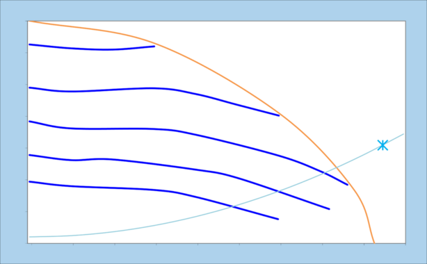
As described in the Flow-Pressure Curves lesson, the performance of the pump is limited by a limit curve, below which every point is reachable depending on the system load and pump speed (Figure 1).

There might be cases though, where the target working point falls outside of the limit curve. In these cases, either a larger pump size can be selected, or multiple pumps can share the work and deliver the target flow rate and pressure.
As an example, let’s analyze the case of a factory-wide re-circulation line, which delivers large flow rates of a chemical to various tools (Figure 2). The hydraulic loop is unrestricted, therefore the system load is a gradual parabola. The required flow rate is so large that it falls out of the operational limit of the pump (Figure 3).

Parallel Pumps Performance
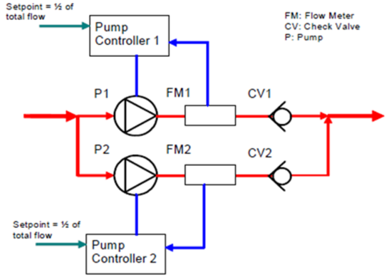
Since the process performance is limited by the flow rate made available by the pump, a possible solution is to install two pumps in parallel (Figure 4). In this way, each pump will deliver half of the target flow rate at the target pressure. The flow rates from each pump will be added together at the junction, so that the overall flow rate in the system is correct.

To estimate the new flow pressure performance of a system of parallel pumps, it is necessary to multiply the flow rate of a single pump by the number of pumps in parallel, while the pressure remains the same (each pump reaches the same pressure, and the flow rates of each pump are added up together, as shown in Figure 5).

Hydraulic Loop Modifications due to Parallel Pumps
In Figure 4 it is shown that not only a second pump was added, but also a pair of check valves (one valve downstream of each pump). These valves are needed to prevent back-flows, in case on pump stops while the other is running (as in the case of a failure).
Levitronix centrifugal pumps don’t have integrated check-valves nor other means to prevent back-flow, therefore they must be installed as an addition to the hydraulic loop.
Control of Parallel Pumps
Since the pumps in parallel should deliver the same pressure, it is common practice to install a set of identical pumps, and operate them at the same working point.
Each pump can have a flow meter installed immediately downstream, and the individual flow rate signals can be sent to the relative pump controller (Figure 6). In this case, the external PLC/SCADA system has the role of summing up the individual flow rates and make sure each pump is delivering the intended amount of fluid.
Redundancy
Having a system composed of pumps in parallel offers the possibility of having a partial or total redundancy, meaning that interrupting one pump will not disrupt the productivity of the plant.
This can be achieved for example by over-sizing the pumping capacity (i.e. installing three pumps in parallel, even though only two would be needed). In this way, if one pump needs maintenance (or it fails), the remaining pumps can increase the speed and make up for the out-of-service pump.
Redundancy is particularly appreciated by customers who have to maximize the factory uptime, reliability and serviceability.
Control of a Redundant System
Conventional centrifugal pumps age with use, therefore, in a redundant system, the pumps should be used alternated (i.e. use only one pump until it needs maintenance or breaks, then use the other pump while the first one gets serviced). This mode of use is shown in Figure 7. Pressure drops in the plant might happen during the switching phase from one pump to the other.

Levitronix pumps don’t mechanically age with use since they don’t have mechanical bearings nor friction, therefore they can be used simultaneously.
Simultaneous use might actually maximize the lifetime of the pumps, since their motors will heat up less. The failure rate of the electronic components inside the motors depends on the operating temperature of the motors, therefore the lower the temperature the higher the uptime.